Inductive Proximity Switch Circuit Diagram plc scada dcs blogspot 2012 01 typical circuit diagram of This is by far the most common starting method available on the market The starting equipment consists of only a main contactor and thermal or electronic overload relay Inductive Proximity Switch Circuit Diagram tehnomagazin Circuits Electronic circuits diagram htmPower Power Supply Power supply schematic inverter schematic Neon lamp inverter circuit power circuit inverter circuit power supply circuit pwm circuit
amazon Electrical Gauges TachometersFulfillment by Amazon FBA is a service we offer sellers that lets them store their products in Amazon s fulfillment centers and we directly pack ship and provide customer service for these products Inductive Proximity Switch Circuit Diagram circuit finder 644 ac line current detectorDescription This circuit will detect AC line currents of about 250 mA or more without making any electrical connections to the line Current is detected by passing one of the AC lines through an inductive pickup L1 made with a 1 inch diameter U bolt wound with 800 turns of 30 35 magnet wire electronics an LED circuit or LED driver is an electrical circuit used to power a light emitting diode LED The circuit must provide sufficient current to light the LED at the required brightness but must limit the current to prevent damaging the LED
plc scada dcs blogspot PLC program for star delta starterThis is a starting method that reduces the starting current and starting torque The device normally consists of three contactors an overload relay and a timer for setting the time in the star position starting position Inductive Proximity Switch Circuit Diagram electronics an LED circuit or LED driver is an electrical circuit used to power a light emitting diode LED The circuit must provide sufficient current to light the LED at the required brightness but must limit the current to prevent damaging the LED satsleuth Schematics aspxElectronic Circuit Schematics Note that all these links are external and we cannot provide support on the circuits or offer any guarantees to their accuracy
Inductive Proximity Switch Circuit Diagram Gallery
pnp proximity sensor wiring dolgular com for inductive diagram, image source: email-verify.co
Sinking+Two Wire+Inductive+Proximity+Sensor, image source: www.diagramschematics.us
inductive proximity switch capacitive threaded cylindrical rectangular_type of switches_how to install a dual battery system in boat phase changer circuit anderson plug wiring camper traile, image source: farhek.com
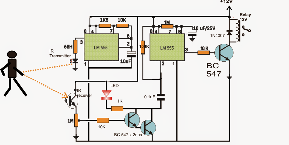
555+proximity+detector+circuit, image source: www.homemade-circuits.com
proximity sensors 11 638, image source: mechaplanet.org
pnp wiring diagram light curtain type sfb ver i o circuit and new inductive proximity sensor, image source: www.diagramschematics.us
inductive proximity sensor, image source: geniusdevils.com

ir proximity sensor circuit, image source: www.electroschematics.com
B, image source: wiringdiagram.geoprivacyhelper.com
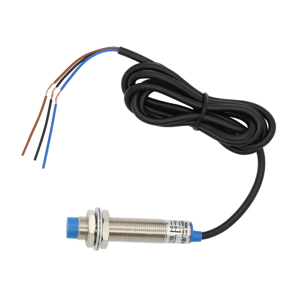
3d printer sensor LJ12A3 4 Z BX Inductive Proximity Sensor Detection Switch NPN DC6 36V 4mm, image source: www.odicis.org
Inductive proximity sensor, image source: www.14core.com

inspirational inductive proximity sensor wiring diagram wiring of 5 wire proximity sensor wiring diagram, image source: studiomotiv.net
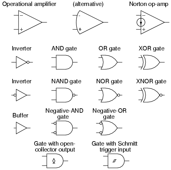
proxy, image source: forum.allaboutcircuits.com
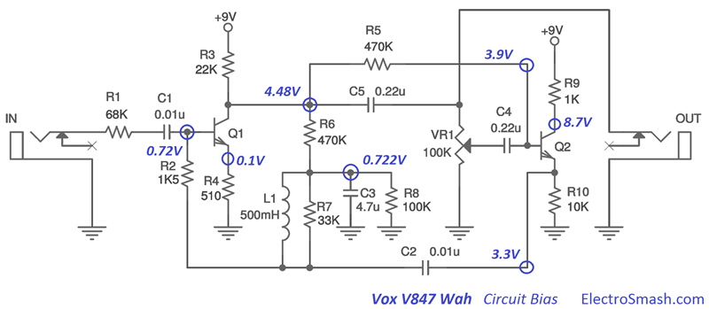
vox v847 circuit bias, image source: www.electrosmash.com
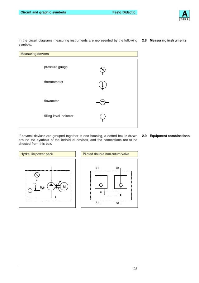
festo electro hydraulics basic levelstextbook 23 638, image source: www.slideshare.net
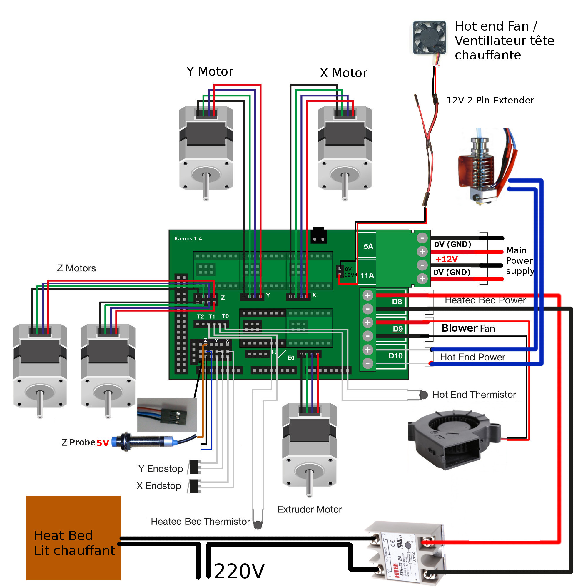
ramps_general_view3, image source: www.modelbouwforum.nl
World_Physical_Blank_Map%20rotated, image source: freerunsca.org

0 comments:
Post a Comment