
Timer Switch Diagram amazon Switches Plug In Switches TimersFAVOLCANO CN101 DC 12V 16A Digital LCD Power Programmable Timer Time Switch Relay Amazon Timer Switch Diagram amazon Switches Wall Switches Timer SwitchesUxcell a12031200ux0078 Power Programmable Timer Time Switch Relay Wall Timer Switches Amazon Industrial Scientific
plcacademy ladder logic examplesLadder logic examples or examples of PLC programs is a great way to learn ladder logic Check out my list of all the best examples of PLC programs Timer Switch Diagram circuitsgallery 2012 02 astable multivibrator using ne 555 Astable Multivibrator using NE 555 timer IC Circuit diagram and working Gallery of Electronic Circuits and projects providing lot of DIY circuit diagrams Robotics Microcontroller Projects Electronic development tools on and off switch circuitCircuit Diagram The circuit diagram for the touch ON and OFF switch circuit is shown in the below image Components Required 1 x 555 Timer
circuitsgallery 2011 09 remote controlled lamp circuit htmlRemote Control Light Circuit Diagram Using 555 Timer Gallery of Electronic Circuits and projects providing lot of DIY circuit diagrams Robotics Microcontroller Projects Electronic development tools Timer Switch Diagram on and off switch circuitCircuit Diagram The circuit diagram for the touch ON and OFF switch circuit is shown in the below image Components Required 1 x 555 Timer 555 timer IC is an integrated circuit chip used in a variety of timer pulse generation and oscillator applications The 555 can be used to provide time delays as an oscillator and as a flip flop element
Timer Switch Diagram Gallery
leviton timer switch wiring diagram copy leviton ltb30 1lz fan timer install youtube maxresdefault switch of leviton timer switch wiring diagram, image source: www.diagramschematics.us

component fuse circuit symbol repin image diagram computer driven eight channel programmable sequencer for neon switch sche thumbnail_fuse circuit_ne555 timer circuits varistor cir, image source: ccuart.org


2012 12 05_190847_maintaintemprelay, image source: www.justanswer.com
video on how to wire a three way switch throughout single pole light wiring diagram, image source: www.diaoyurcom.com


c565795298451869c48748d98c865117, image source: www.pinterest.com

hqdefault, image source: www.youtube.com
Basic+ignition+wiring+diagram, image source: smighterofwrongs.blogspot.com
paragon defrost timer 8145 20 wiring diagram paragonwire jpg resize d665 2c357 6ssl d1 to, image source: codecookbook.co


maxresdefault, image source: www.youtube.com

maxresdefault, image source: www.youtube.com
maxresdefault, image source: www.youtube.com
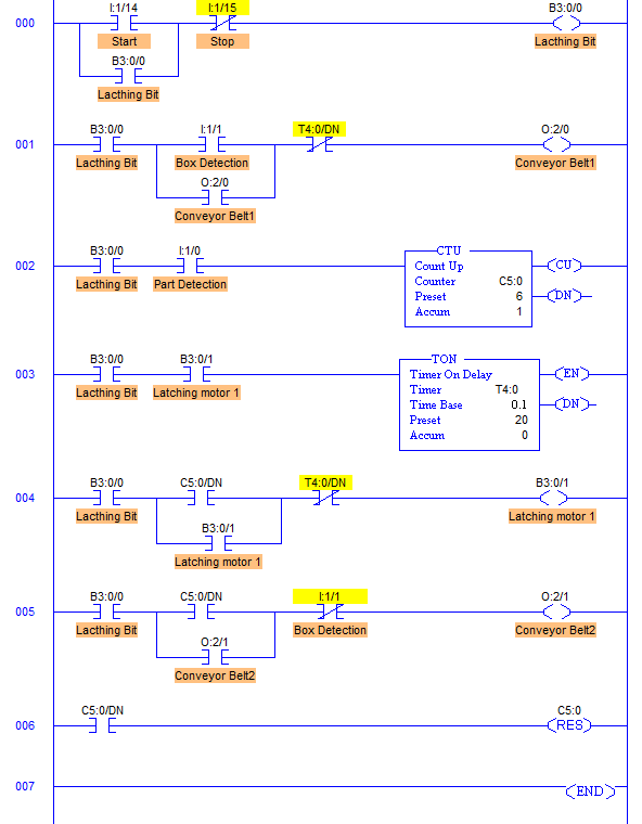
plc program count pack parts conveyor 02, image source: www.sanfoundry.com

28 10 10 09 11 44 746844, image source: mesnotices.20minutes.fr
zachman framework diagram, image source: cssmith.co

image8611, image source: www.keywordhut.com


Arduino LED Blinking, image source: circuitdigest.com
TB961_2, image source: www.crnt.co.jp


0 comments:
Post a Comment