Zero Speed Switch Circuit Diagram instrumentationtools SwitchesHome Switches Zero Speed Switch Working Principle Switches Zero Speed Switch Working Principle S Bharadwaj Reddy 3 Comments Share Zero speed switches ZSS Proximity switches Circuit Diagram Operation May 29 2016 Zero Speed Switch Circuit Diagram machineryequipmentonline electric equipment troubleshooting Plug stop and anti plug circuits To halt a motor or to stop a running motor a common method is to remove the supply voltage and allow the motor and load to Sections zero speed switch circuit diagram what is the circuit diagram for a zero speed anti plugging switch forward circuit of equipment
conveyorcomponents product zero speed controlZero Speed Control Click image to enlarge The output contacts of the Model CMS can control up to two separate circuits one for machinery shutdown and one for an alarm Model CMS Typical Conveyor Wiring Diagram Model CMS Zero Speed Control Model CMS Zero Speed Control Typical Mounting Arrangement Zero Speed Switch Circuit Diagram forums mrplc index php topic 13921 zero speed sensor circuitMay 03 2008 Hi Can anyone please give me a simplified circuit diagram for a zero speed sensor which uses a Namur proximity sensor to count pulses I want the circuit www2 schneider electric documents original equipment Safety Chain Solution Zero Speed detection Chain structure The circuit diagram SCS07 0310D is a conceptual schematic diagram and is limited to present the safety function with only the
maxigard pdf A5000GEC install pdf5 0 Wiring the A5000GEC Zero Speed Switch 5 1 Power connections and relay connections to the A5000GEC Zero Speed Switch are shown on figure 3 page 4 Also figure 4 5 page 5 6 show typical wiring diagrams 5 2 Connect 120 VAC power to the RED wire and neutral to the WHITE wire Connect Zero Speed Switch Circuit Diagram www2 schneider electric documents original equipment Safety Chain Solution Zero Speed detection Chain structure The circuit diagram SCS07 0310D is a conceptual schematic diagram and is limited to present the safety function with only the autotechcontrols downloads PS111 Zero Speed Switch PS112 PS111 Zero Speed Switch and PS112 Adjustable Speed Sensor Installation Operation Manual Sales and Marketing PS111 Zero Speed Switch Wiring Diagram Wire the switch in accordance with the diagram below Outline Dimensions
Zero Speed Switch Circuit Diagram Gallery

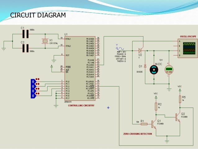
to control the speed of dc motor simple project 9 638, image source: www.slideshare.net
BT136 Triac Interfacing with AVR ATmega16 Microcontroller Circuit Diagram 1024x517, image source: thetada.com
SCR Pulse Control Circuit, image source: www.circuitstoday.com

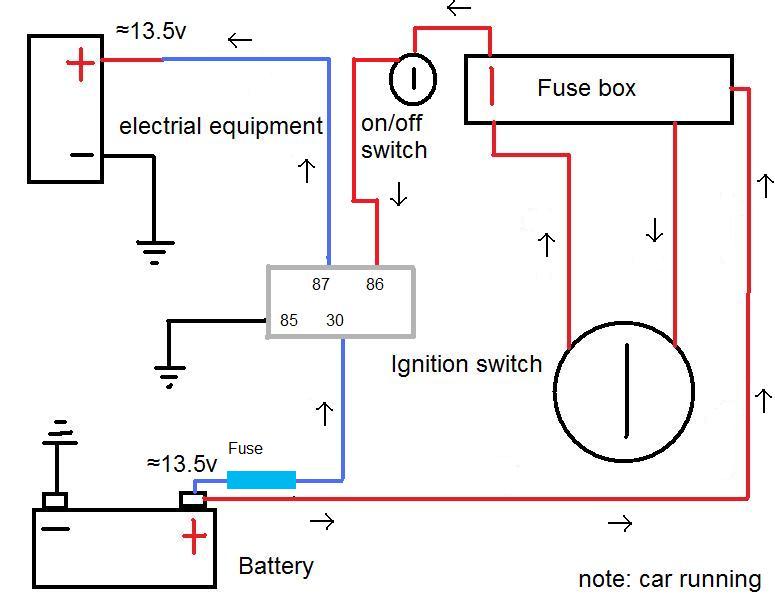
878225, image source: www.thesamba.com
main qimg 974ed3370260c509f58290f10e225f9f c, image source: www.odicis.org
aclatch, image source: www.bowdenshobbycircuits.info
0996b43f80231a23, image source: www.justanswer.com

hqdefault, image source: www.youtube.com
Hydraulics_03042016_Schematic, image source: www.machinerylubrication.com
Auto Transformer Starter, image source: www.electronicshub.org

SpeedSensor Tutorial Schema, image source: brainy-bits.com

CNX_Psych_12_03_Persuasion2, image source: ccuart.org

US06632072 20031014 D00006, image source: www.google.com

maxresdefault, image source: www.youtube.com
lpfp, image source: www.useasydocs.com
SPD 3648350BLDC lg, image source: www.electricscooterparts.com

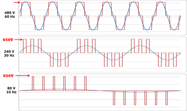
pwm output, image source: www.vfds.com

hqdefault, image source: www.youtube.com

0 comments:
Post a Comment