Gas Valve Wiring Diagram to view4 26Oct 18 2013 This one covers how the gas valve on the millivolt system is wired This video is part of the heating and cooling series of training videos made to accompany my websites graycoolingman Gas Valve Wiring Diagram wiring basics for Any wiring diagrams I show you will be for a standing pilot Before we wire the system let s look at a gas valve Figure 6 This is what the terminal block looks like on a 24 V standing pilot gas valve
fm xweb frymaster service udocs Instruction PDFs 819 5739 SEP ROBERTSHAW TO HONEYWELL MILLIVOLT GAS VALVE CONVERSION 807 1603 NAT AND 807 1604 PRO wiring per the wiring diagram below NOTE If the existing wire terminals do not fit the terminals on the replacement gas valve cut them off and replace them with the terminals provided in this kit Crimp and solder the new Gas Valve Wiring Diagram s3 supplyhouse manuals 1249544894162 Honeywell VS820 Product These gas controls combine a Lite Rite manual gas cock safety shutoff Pilotstat assembly Fig 4 Typical Powerpile system wiring diagram 1 Install Powerpile thermostat limit control if re quired and Powerpile generator according to The automatic safety shutoff valve blocks gas flow h mac product catalogs sterling Sterling QVED QVES Wiring TYPICAL WIRING DIAGRAM MANUAL INDOOR GAS FIRED UNIT HEATERS AND DUCT FURNACES Standard Natural Vent or Power Vented furnace should be located as close to the gas valve and controls as possible Each unit heater duct furnace WIRING DIAGRAM NO UNIT TYPE GAS TYPE UNIT SIZE GAS CONTROL STAGE Natural Gas LP Gas
thingssoughtafter ebay product info white rodgers b57ra68e INSTALLATION INSTRUCTIONS DESCRIPTION The 857 Model E Midgitrol Combination Gas Valve Regulator adjustment provides all manual and automatic gas control functions Gas valve wiring diagram ADJUSTMENT PILOT GAS ADJUSTMENT MILLIVOLTMETER TEST Remove the cover screw fig 3 and turn the Gas Valve Wiring Diagram h mac product catalogs sterling Sterling QVED QVES Wiring TYPICAL WIRING DIAGRAM MANUAL INDOOR GAS FIRED UNIT HEATERS AND DUCT FURNACES Standard Natural Vent or Power Vented furnace should be located as close to the gas valve and controls as possible Each unit heater duct furnace WIRING DIAGRAM NO UNIT TYPE GAS TYPE UNIT SIZE GAS CONTROL STAGE Natural Gas LP Gas applianceassistant f90553 viking free standing gas range pdfviking range corporation product warranty cooking products free standing gas ranges 90 days glass painted porcelain and decorative items
Gas Valve Wiring Diagram Gallery

Beautiful Gas Solenoid Valve Wiring Diagram 92 For Basic Home Wiring Diagrams Pdf with Gas Solenoid Valve Wiring Diagram, image source: www.elvenlabs.com

furnace how can i connect a humidifier to goodman dual fuel magnificent lennox wiring diagram, image source: www.kolnetanya.com
american standard furnace wiring diagram gas free printable of diagrams fax modular jack, image source: cssmith.co
charming volvo penta starter wiring diagram ideas electrical endear, image source: www.masaleh.co
honeywell wifi thermostat wiring diagram wire honeywell thermostat wiring diagram get about wiring diagram, image source: estrategys.co

Nitrox3, image source: www.nuvair.com
Jumping Valve, image source: www.mygasfireplacerepair.com

Cafe Racer Wiring 1, image source: efcaviation.com

post 889 0 91778700 1376583426, image source: broncozone.com

2938f8146dfcebf03170cdc4ed95f0a6a63263a8, image source: www.pakwheels.com
GasDelpg84, image source: www.asge-online.com

hqdefault, image source: www.youtube.com

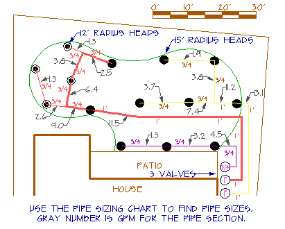
sprinkler22c1, image source: www.irrigationtutorials.com
maxresdefault, image source: www.youtube.com

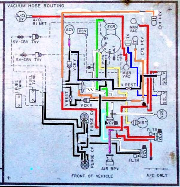
1813_0_9 vacuum hose routing cbr 600, image source: www.kappabikes.xyz
box_type_relay_for_refrigerator, image source: appliancesparts.in

Medical_Gas_System_Rough In, image source: en.wikipedia.org
ME7_w734, image source: br.bosch-automotive.com

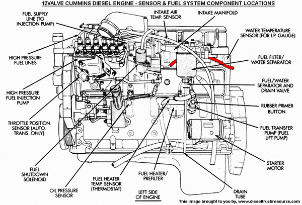
50571d1501310772 starting issues return_line, image source: www.dieselbombers.com

0 comments:
Post a Comment