
Clap Switch Circuit Diagram Using Transistor circuitsarena HOBBY PROJECTS PROJECTS TRANSISTORSCLAP SWITCH USING TRANSISTOR is the artlcle explaining Clap Switch Hobby Circuit for electronics hobbyists that can switch on off a light Fan Radio etc by the sound of clap T Clap Switch Circuit Diagram Using Transistor switchThe pulse of clap which is a trigger for flip flop makes changes to the output state that is complementary reverse Output of flip flop which is in the low current form is unable to drive relay so we have used a current amplifier circuit by using Q4 that is a common emitter circuit
electricaltechnology Basic ElectronicsClap Switch Circuit Electronic Project Using 555 Timer BC 547 Transistors Introduction Clap Switch is a basic Electronics mini project made with the help of the basic components Clap Switch Circuit Diagram Using Transistor clap switch circuit using Simple Clap Switch Circuit using Transistors Tested Last Updated on January 10 2018 by admin Leave a Comment Below is a simple clap switch circuit for electronics amateurs which could turn on off a bulb Fan Radio and so on through the noise of clap clap switch circuitNow you can make a simple clap switch project here you can find all required components circuit diagram working process along with output video
switch using transistorClap Switch using Transistor Posted March 23 2015 by circuit wiring in Switch and Relay Circuits Here the simple circuit diagram of clap switch built using transistors This circuit toggles the LEDs each and every time it detects a clap or tap or short whistle The second 10uF is charged through the 5k6 and 33k and each time a sound Clap Switch Circuit Diagram Using Transistor clap switch circuitNow you can make a simple clap switch project here you can find all required components circuit diagram working process along with output video circuits clap on clap off switchA Clap On Clap Off switch is an interesting concept that could be used in home automation It works as a switch which makes devices On and Off by making a clap sound You can see the connections in above clap on clap off circuit diagram Initially the transistor is in OFF state because there is not enough 0 7v base emitter
Clap Switch Circuit Diagram Using Transistor Gallery
Clap Switch Circuit, image source: circuitdigest.com


Sensitive Clap Switch, image source: www.electroschematics.com
Clap On Clap Off Switch, image source: circuitdigest.com

Clap Switch, image source: circuitdigest.com

Circuit diagram of off timer with alarm, image source: electronicsproject.org

2680184924, image source: thetada.com
circuit to store a two digit seven segment display data 24c02 part of_seven segment display circuit diagram_high pass filter circuit rc coupled amplifier sample and hold radio board smal, image source: farhek.com

th?id=OGC, image source: circuiteasy.com

audio activated relay switch circuit, image source: www.circuitdiagram.org

D type flip flop circuit, image source: circuitdigest.com

usb relay switch output module board controller 12v ebay controlled_electrical relay switch_transistor relay circuit 4 pin wiring diagram 8 about wire automotive power different types of rel, image source: farhek.com

th?id=OGC, image source: circuiteasy.com


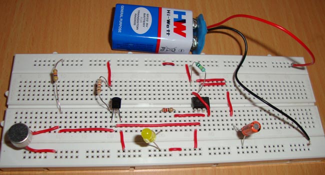
Simple+condenser+microphone+mini+audio+sound+amplifier+circuit+schematic+with+BC547, image source: www.circuitsgallery.com
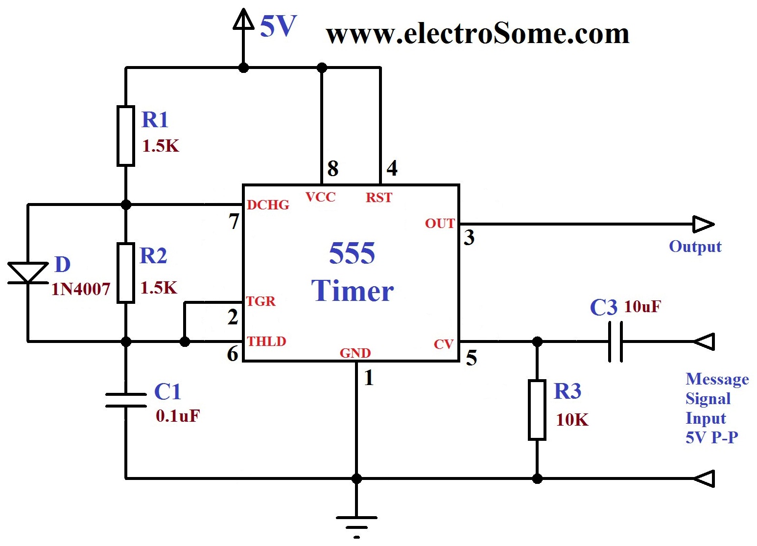
FM Generation using 555 Timer, image source: electrosome.com
electronic mosquito repeller9, image source: www.circuitstoday.com

electronic circuits page next gr resistance soldering circuitry_application of triac_1uf capacitor code types of diodes 47uf tantalum starter connection diagram how to wire 2, image source: farhek.com

Servo using 555 timer, image source: rookieelectronics.com

dark sensor 2, image source: www.buildcircuit.com

police siren with ldr2, image source: www.buildcircuit.com


0 comments:
Post a Comment