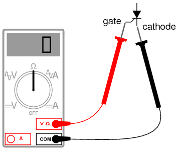
Scr Switch Circuit Diagram circuitstoday battery charger circuit using scri known more about this project t battery charger circuit using scr please help me Scr Switch Circuit Diagram circuitstoday how to test an scrTesting SCR using a multimeter A multimeter can be used to test SCRs quite effectively The first procedure is to check the diode action between the gate and cathode terminals of the SCR This test is just like what you have done in the case of testing a silicon diode see testing a silicon diode Now put the multimeter selector switch in a high
electronic circuits ldr circuit diagramThis simple LDR circuit diagram shows how you can use the light dependent resistor to make an LED turn on and off depending on the light Scr Switch Circuit Diagram electronicecircuits Electronic CircuitsLow Ripple Regulated Power Supply Circuit Diagram This circuit may be used where a high current is required with a low ripple voltage such as in a high powered techlib electronics games htmlOne base unit and several contestant stations are wired together as shown in the block diagram above Most small signal PNP transistors will substitute for the 2N4403
circuitdiagram 12v solar led night activated lamp htmlFigure shows a great project schematic of a 12V solar LED night activated lamp circuit This is a versatile project and can be used for variety of purposes Scr Switch Circuit Diagram techlib electronics games htmlOne base unit and several contestant stations are wired together as shown in the block diagram above Most small signal PNP transistors will substitute for the 2N4403 gmcws Tech dsimmons onan onan htmlSTARTING CIRCUIT Figure 1 Pressing the START switch S3 or the Remote Switch will power the starter relay K1 by applying a ground through the HOLD RELAY contact K2a normally closed contact
Scr Switch Circuit Diagram Gallery

maxresdefault, image source: www.youtube.com

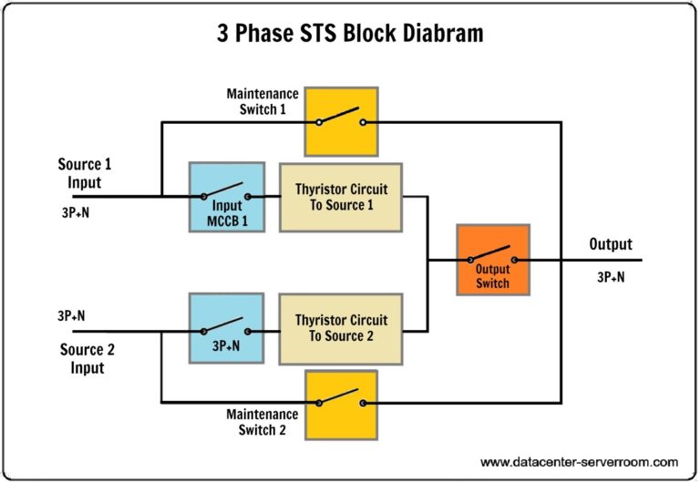
Static Transfer switch for server room and Datacenter in UAE 768x530, image source: www.datacenter-serverroom.com
component scr testing of thyristor by hot method youtube basic electronic circuit design diy part a with fluke transistor t_transistor scr_bjt npn transistor big basic of b81, image source: togelll.com

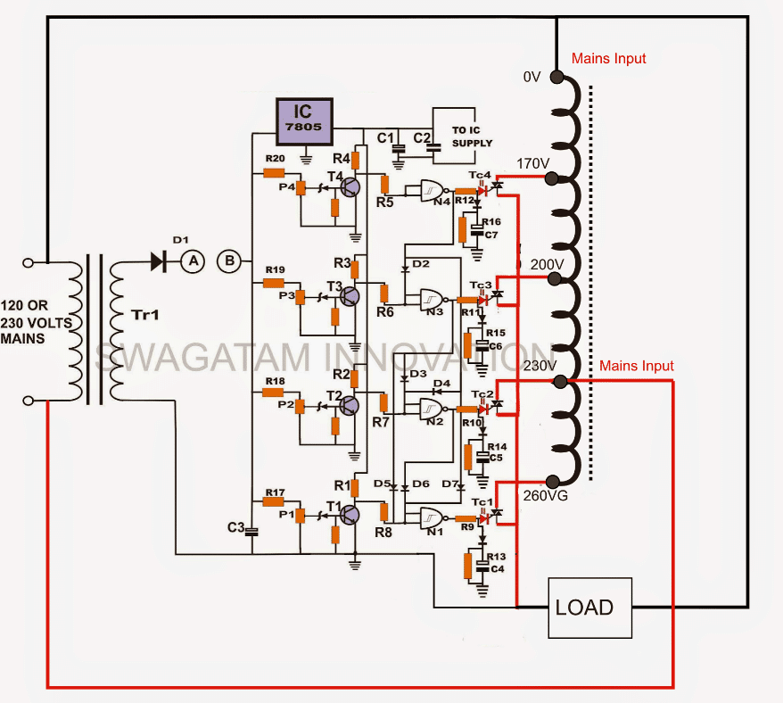
TRIACCONTROLLEDSTABILIZERCIRCUIT, image source: www.homemade-circuits.com

NV_0202_Marston_FIG9, image source: www.nutsvolts.com

LED2Bdimmer, image source: www.homemade-circuits.com
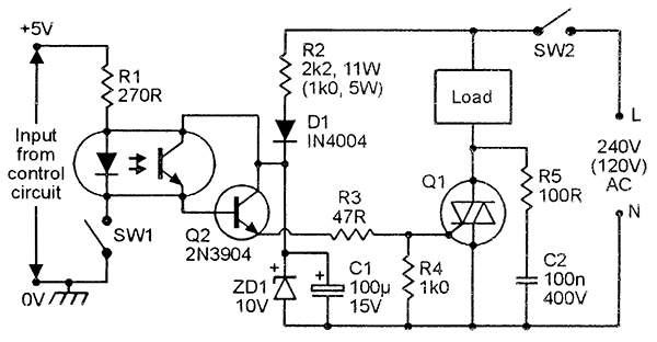
DC_Control_for_Triacs_Circuit_Diagram 1366342665, image source: www.eeweb.com

03207, image source: www.allaboutcircuits.com

ozonegeneratorcircuit, image source: www.homemade-circuits.com

a1ebcad8b6e912844248fc5e4b6ebade, image source: www.pinterest.com

jqLA9, image source: electronics.stackexchange.com
tl494 entegresi ile 20v 100v step up devresi mcufreak devrede r4 ve r5 in1 5v olarak getirir_tl494 boost converter_operation of diode zener used as voltage regulator aluminum wiring motor, image source: farhek.com
Adjustable Regulated Power Supply using LM7805 Circuit Schematic Diagram, image source: circuitswiring.com

block diagram of power supply, image source: www.odicis.org

03302, image source: allaboutcircuits.com
triac lamp dimmer circuit, image source: elektronikforumet.com
emct_2e_5 1, image source: www.industrial-electronics.com
circuit symbol thyristor scr 01, image source: www.electronics-notes.com
diac_5, image source: www.dirind.com


0 comments:
Post a Comment