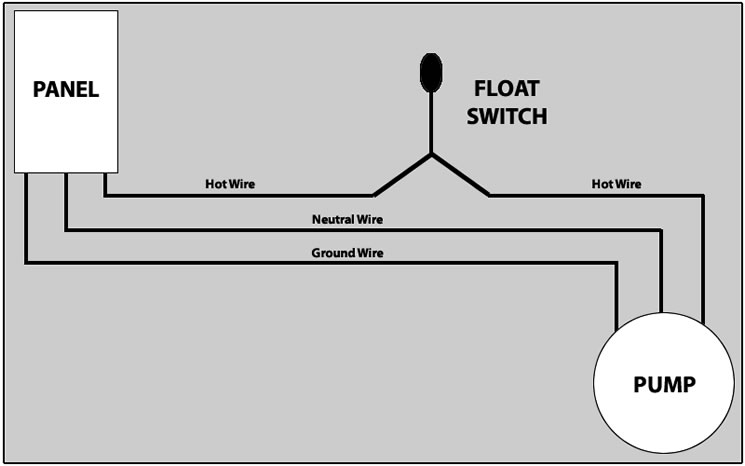
Float Switch Circuit Diagram septicsolutions store alarms floats htmLevel alert alarms can be used to monitor the liquid levels in a tank The most common form of this is our High Water Alarms Use high water alarms to Float Switch Circuit Diagram ijyam blogspot 2013 04 electrical wiring diagram star delta htmlApr 15 2013 This article is intended to diagrammatically demonstrate the concept of the wiring principle of a star delta wye delta motor control and power circuit when using a PLC Programmable Logic Controller ladder program to control the switching of a 440 volts induction motor
amazon Boating Boat Plumbing Bilge PumpsAmazon AURELIO TECH 12V Automatic Submersible Boat Bilge Water Pump 750GPH Auto With Float Switch Sports Outdoors Float Switch Circuit Diagram amazon Boating Boat Plumbing Bilge PumpsAmazon Amarine made Automatic Submersible Boat Bilge Water Pump 12v 750gph Auto with Float Switch new A Sports Outdoors solorb elect solarcirc scc3SCC3 12 Volt 20 Amp Solar Charge Controller A kit with the circuit board and parts for this circuit is available from CirKits SCC3 12 Volt 20 Amp Solar Charge Controller
learningelectronics circuitsLearn to build electronic circuits Vol I DC Vol II AC Vol III Semiconductors Vol IV Digital Vol V Reference Float Switch Circuit Diagram solorb elect solarcirc scc3SCC3 12 Volt 20 Amp Solar Charge Controller A kit with the circuit board and parts for this circuit is available from CirKits SCC3 12 Volt 20 Amp Solar Charge Controller instructables id Battery Float ChargerDec 31 2015 Most older battery charger units designed to bulk charge which is a reltively fast process to recharge a depleted battery Though if you permanently leave a fast charger on your battery it will overcharge and destroy the battery or in best case it simply switch itself off after an initial full charge and leave the battery alone
Float Switch Circuit Diagram Gallery
cp1 fill only electronic water level sensor of float level switch wiring diagram, image source: www.vivresaville.com
float switch installation wiring and control diagrams of float level switch wiring diagram 2, image source: www.vivresaville.com
septic tank float switch wiring diagram 3 way switch wiring 1 of float level switch wiring diagram, image source: estrategys.co

FloatSwitchWiring, image source: efcaviation.com
a c contactor wiring diagram inspirationa how does a contactor work what is wiring best diagram hbphelp of a c contactor wiring diagram 1, image source: sandaoil.co
simple 2000 jetta wiring diagram vw system wiring diagrams best septic tank treatment diagram, image source: www.diaoyurcom.com

maxresdefault, image source: www.youtube.com

hand off auto wiring diagram electric hand off auto switch wiring in hand off auto wiring diagram, image source: www.gsmx.co

flotec submersible pump wiring diagram water diagram, image source: eidetec.com

hand off auto wiring diagram electric hand off auto switch wiring in hand off auto wiring diagram, image source: www.sewacar.co

pump, image source: www.homemade-circuits.com
intro_2, image source: www.ia.omron.com
RelayDiagram, image source: www.inceptiontechnologies.com
US06632072 20031014 D00005, image source: www.google.com
220v welder plug wiring diagram best of generous 240 volt plugs electrical circuit diagram ideas of 220v welder plug wiring diagram, image source: thetada.com
four way switch wiring diagram elegant 4 way switch wiring diagrams autobonches arresting diagram of four way switch wiring diagram for four way switch wiring diagram, image source: studiomotiv.net
The System Layout, image source: www.water-level-controller.com

89_96_uk_XV535, image source: vsoc.org.uk

8M0078553, image source: www.marineengine.com

0 comments:
Post a Comment