Switch Mode Inverter Circuit Diagram circuitstoday simple 100w inverter circuit100Watt Inverter Circuit Inverter circuits are among the easiest circuits to build for newbies Here is the circuit diagram of a simple 100 watt inverter using IC CD4047 and MOSFET IRF540 Switch Mode Inverter Circuit Diagram microcontrollerslab circuit diagram pure sine wave invertersine wave inverter circuit diagram using microcontroller Arduino and program code SPWM using pic16f877a microcontroller
dc 220v ac converter circuitInverters are often needed at places where it is not possible to get AC supply from the Mains An inverter circuit is used to convert the DC power to AC power Switch Mode Inverter Circuit Diagram and output Input voltage A typical power inverter device or circuit requires a relatively stable DC power source capable of supplying enough current for the intended power demands of the system 320volt en sg3524 dc ac inverter projesi 250w 5000wSG3524 PWM control IC based on the DC to AC inverter circuit transformer change and the number of transistors compared to the 250w 5000w power between can give
circuitstoday pwm inverter circuitSimple PWM inverter circuit using SG3524 This PWM inverter circuit has 12V input 220V output and 250 watt output power Output power can be extended Switch Mode Inverter Circuit Diagram 320volt en sg3524 dc ac inverter projesi 250w 5000wSG3524 PWM control IC based on the DC to AC inverter circuit transformer change and the number of transistors compared to the 250w 5000w power between can give work is licensed under a Creative Commons Attribution NonCommercial 2 5 License This means you re free to copy and share these
Switch Mode Inverter Circuit Diagram Gallery

adjustable+smps+circuit, image source: www.circuitsarena.com
circuit diagram of pnp transistor beautiful transistors dc motor power amplifier issue electrical the pnp of circuit diagram of pnp transistor, image source: thespartanchronicle.com

smps%2Bpower%2Bsupply%2B350W%2Bct, image source: www.elcircuit.com
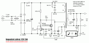
27_1299601817, image source: www.edaboard.com

simple_smps_3 300x148, image source: www.pocketmagic.net
Very Wide Input Voltage Range Off line Flyback Switching Power Supply, image source: www.next.gr

residual current device, image source: wiringdiagram.karaharmsphotography.com

circuit diagram of advance mini ups, image source: bestengineeringprojects.com

hqdefault, image source: www.youtube.com
.jpg)
ImageForArticle_13861(2), image source: www.azom.com
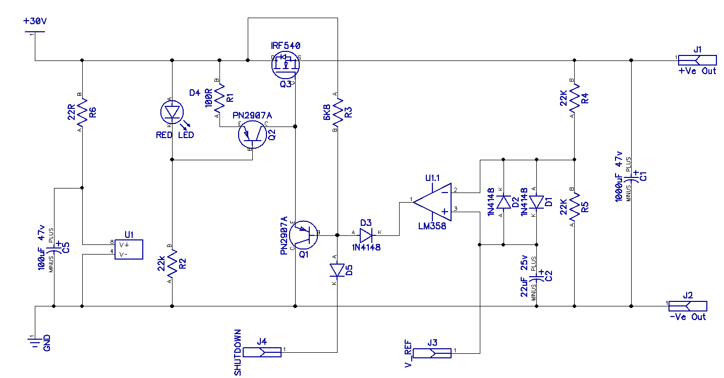
HyU2l, image source: electronics.stackexchange.com
simple_smps, image source: www.pocketmagic.net

PSU 0, image source: gerrysweeney.com

royer%2Binduction%2Bheater%2Bcircuit, image source: www.homemade-circuits.com

a3m_f0, image source: wiki.analog.com

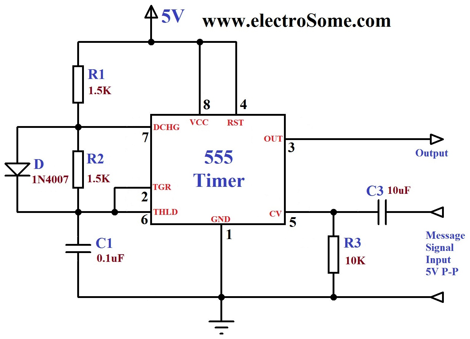
FM Generation using 555 Timer, image source: electrosome.com

Figure_1, image source: www.eetimes.com

fig6, image source: technologydynamicsinc.com

maxresdefault, image source: www.youtube.com
2wire_rs485_fig3, image source: advantech-bb.com

0 comments:
Post a Comment