Layer 3 Switch Network Diagram Model Layer Protocol data unit PDU Function Host layers 7 Application Data High level APIs including resource sharing remote file access 6 Presentation Translation of data between a networking service and an application including character encoding data compression and encryption decryption 5 Layer 3 Switch Network Diagram vrfs to maintain security zones in The number of overlay technologies available today for the datacenter are numerous and highly functional The flexibility they provide enables security zone enforcement and physical portability of hosts more seamlessly among other benefits However a few risks in deploying popular layer 2 overlay technologies are vendor lockdown scalability
zytrax tech layer 1 cables tech lan htmLAN Wiring Pinouts 10base T 100base TX T4 1000base T 10Gbase T Note These pages were originally written when the world was young and 10m LANs were nose bleedingly fast They have been updated over the years but still contain some now long in the tooth aka legacy stuff about crossed cables especially Layer 3 Switch Network Diagram documentation series physical Diagramming switch stacks in a physical network is accomplished in the way shown here Since a switch stack operates and manages very much like a chassis switch but physically appears as two separate switches it makes sense to diagram it as a pseudo single device using the background box 05 2012 Hi I was reading wikipedia about Multicast messages and found this Some well known Ethernet multicast addresses 14 Ethernet multicast
Layer Security TLS and its predecessor Secure Sockets Layer SSL which is now deprecated by the Internet Engineering Task Force IETF are cryptographic protocols that provide communications security over a computer network Several versions of the protocols find widespread use in applications such as web Layer 3 Switch Network Diagram 05 2012 Hi I was reading wikipedia about Multicast messages and found this Some well known Ethernet multicast addresses 14 Ethernet multicast escotal osilayer htmlOSI Layer Model for concentrators Hubs Repeaters are found in the Physical Layer Switches Bridges Wireless Access Point are found in the Data Link Layer Multilayer Switch are found in both the Data Link Layer and Network Layer Routers are found in the Network Layer Gateway are found in All 7 of the OSI Layers Brouter are found in both the Data Link and Network Layer
Layer 3 Switch Network Diagram Gallery
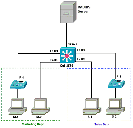
98523 8021x cat layer3 01, image source: www.cisco.com
pict multilayer switch cisco switches and hubs vector stencils library, image source: www.conceptdraw.com
pict layer 2 remote switch cisco switches and hubs vector stencils library, image source: www.conceptdraw.com
VLAN Diagram4, image source: blog.michaelfmcnamara.com
di8oLRL4T, image source: www.clipartbest.com
226680, image source: www.cisco.com
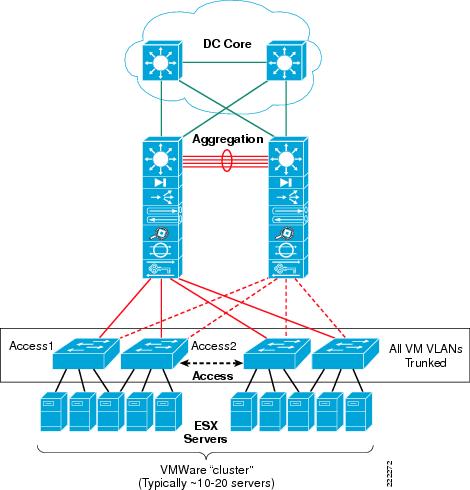
222272, image source: www.cisco.com
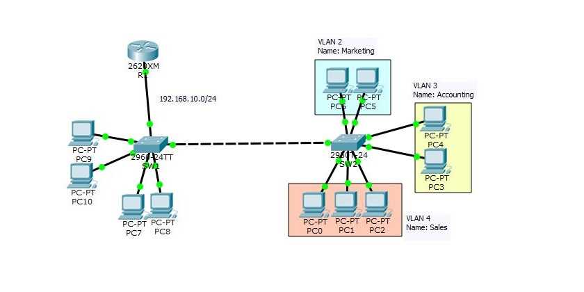
Configure VLAN on Cisco Switches, image source: www.technig.com

vlan, image source: wozney.ca
th?id=OGC, image source: giphy.com
Slide3, image source: whatisccna.blogspot.com
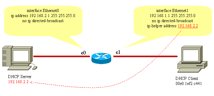
27470 100a, image source: www.cisco.com
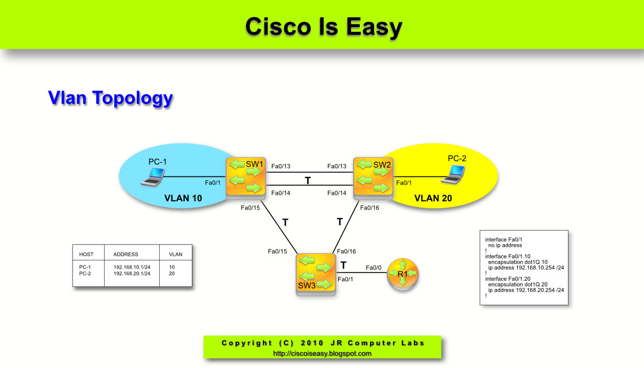
1 Vlan Topology, image source: ciscoiseasy.blogspot.com

rj45 pinout, image source: www.networkel.com
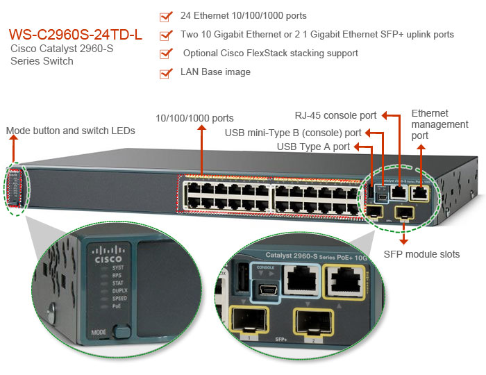
WS C2960S 24TD L, image source: 91sec.blogspot.com
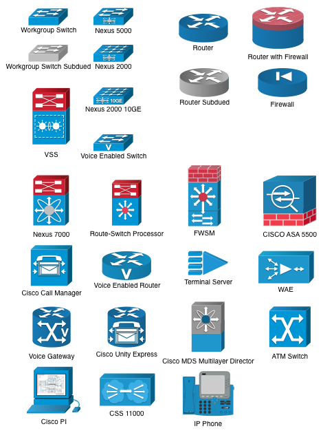
preview_fH2BU7o, image source: stenciltown.omnigroup.com
network diagram, image source: www.techonia.com
network security Message Authentication Code 1024x512, image source: www.keyboardbanger.com
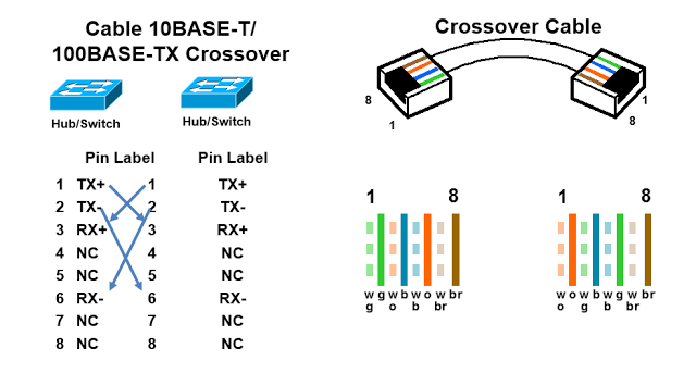
rj45 pinout crossover, image source: networkel.com
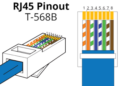
rj45 pinout b, image source: networkel.com

0 comments:
Post a Comment