4 Pin Ignition Switch Circuit Diagram continuouswave whaler reference ignitionSwitch htmlDescription and schematic diagram for wiring for typical outboard engine ignition switch particularly OMC or BRP 4 Pin Ignition Switch Circuit Diagram unit wiring Flasher Unit Wiring Diagram 2 Pin Mk2 MGBs used a rectangular 2 pin indicator flasher unit SFB115 was V8s have the same part number listed but shown as 2 pin in the diagram and the same Any electrical circuit will lose
pelicanparts Porsche HomeTo remove the ignition key cylinder first begin by pulling out the rubber ignition switch surround upper left Then turn the ignition switch to position 1 ignition ON and insert a large paper clip into the release hole in the 4 Pin Ignition Switch Circuit Diagram davebarton pdf coolingfandiagrams pdfSPST vs SPDT Relays What s the difference Single Pole Single Throw SPST This relay will be identified as having a middle 87b spade or no middle spade at all This is the most common relay used for fog lights or other simple circuits autoshop101 forms elec07 pdfAppendix A A 2 TOYOTA Technical Training IGNITION SWITCH A key operated switch with several positions which allow various circuits to become operational including the primary ignition circuit
useasydocs details GM 7pinHEI htmThe 7 Pin HEI Module With a GM HEI 7 pin and 8 pin modules the ignition module wires you need to know about are tach signal is a purple wire with a white trace pin R goes to Ampseal OPTOIN pin 30 ground the Ampseal OPTOIN pin 31 at the distributor advance control signal is a white wire pin E goes to Ampseal pin 12 4 Pin Ignition Switch Circuit Diagram autoshop101 forms elec07 pdfAppendix A A 2 TOYOTA Technical Training IGNITION SWITCH A key operated switch with several positions which allow various circuits to become operational including the primary ignition circuit megamanual ms2 GM 7pinHEI htmGeneral Motors HEI Ignition Control with MegaSquirt II There were a number of different kinds of General Motors HEI modules 4 pin module electronic ignition but doesn t do computer timing control top left 7 pin module large electronic module that does timing control used with coil in cap distributors top right 7 pin module small electronic
4 Pin Ignition Switch Circuit Diagram Gallery
new wiring diagram for ignition switch ignition switch wiring diagram fitfathers me, image source: estrategys.co

diagram 12v pin relay wiring bosch amazing picture ideas with 5, image source: deltagenerali.me
subst2017l, image source: www.kirmanual.com

2012 04 30_123511_key_switch_mercury, image source: www.justanswer.com

926445d1428512968 car won t start not getting 12v power to starter solenoid porsche 996 starter circuit, image source: rennlist.com

blackmax bm portable generator parts of wiring diagram coil ignition, image source: www.pressauto.net
4 Wire Ignition Switch Diagram the back for connections a battery connector a accessory connector a starter connector and a ignition connector, image source: www.replicasuper.com
voltage regulator rectifier wiring diagram_623630, image source: www.gridgit.com
144419d1191391091 compressor relay 83 300d turbo compressor clutch control, image source: www.benzworld.org
latest baldor wiring diagram help wiring baldor motor and 220v diagram gooddy org, image source: www.diaoyurcom.com
wiring diagram for key start 12 volt alternator conversion in farmall cub to a, image source: codecookbook.co

838751d1401390724 alternator replacement nightmare 993 alt batt starter wiring, image source: rennlist.com
turn signal_relay, image source: support.electricscooterparts.com
fine 240sx headlight wiring diagram inspiration of 1991 nissan 240sx wiring diagram, image source: www.vivresaville.com

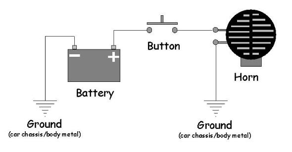
8343d1390409272 i need help wiring my sportsman 400 horn image001, image source: atvconnection.com
77174684, image source: www.partdeal.com

wires, image source: www.tamahuproject.org
startercircuitp7xrbgkctw, image source: www.forabodiesonly.com
System_Check_Wiring_Harness_Colors, image source: www.whalercentral.com

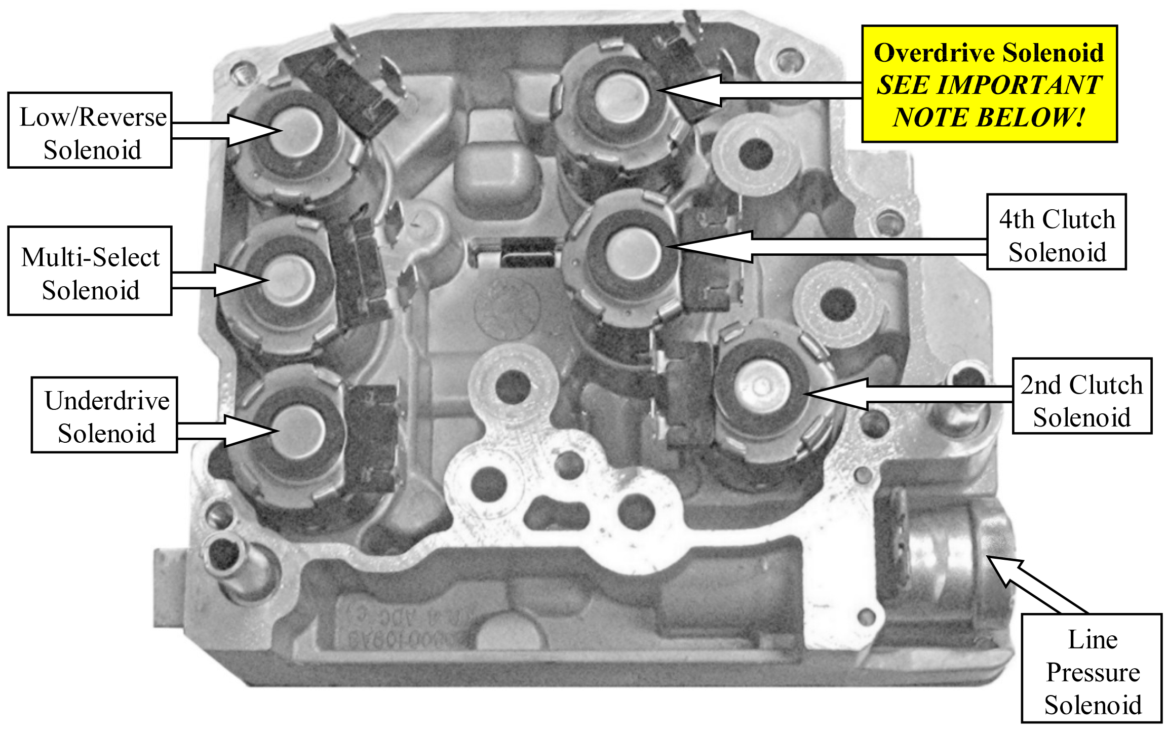
45RFE_ _545RFE_Tech_Info__Solenoid_ID, image source: www.sonnax.com

0 comments:
Post a Comment