Foot Pedal Switch Wiring Diagram Switch how to order 1 800 676 6123 sales progressiveautomations progressiveautomations foot switch wiring diagram specifications To wire the actuator to the foot switch for double action extention retraction make the connections Foot Pedal Switch Wiring Diagram content uploads 2015 12 Foot Switch see wiring diagram notes on wiring 1 the switch is typically wired into one side of the electrical circuit normally the hot side if applicable 2 follow all applicable electrical codes and consult an electrician with questions 3 the white and black lead colors on the foot switch cable have no relevance to household wiring electrical
to view7 00Dec 22 2016 When using some of the power tools you need to use both hands and also control on off the tool In this case for my drill press I wanted a better control when to start it without moving it Foot Pedal Switch Wiring Diagram guideFoot Switch Selection Guide Foot switches can be used to turn electrical equipment on and off with the foot freeing the hands to perform other operations or providing ergonomic improvement to a workstation Foot switch and foot pedal applications often require specific electrical ratings enclosures pedal actions cables and other linemaster Documents Product 0001140 522 F20 pdfOn a REGULAR BASIS inspect foot switch frequently to guard against wear damage unlawful alterations or removal of guards or for unusual enclosure deterioration and the like Inspect the entire length of the connecting cord or wiring system from where it
SWITCH WIRING DIAGRAM Works for Hand Remotes as well Negative Terminal Power Source Positive Terminal AC 22 Relay 1 NC 3 NO 5 com AC 22 Relay 1 NC 3 NO 5 com Actuator 4 NO com 4 NO com Down Foot Switch PDL OI Connection To Relay Terminal 4 NC Relay Terminal 14 T2 Battery Negative Terminal Connection To Battery Foot Pedal Switch Wiring Diagram linemaster Documents Product 0001140 522 F20 pdfOn a REGULAR BASIS inspect foot switch frequently to guard against wear damage unlawful alterations or removal of guards or for unusual enclosure deterioration and the like Inspect the entire length of the connecting cord or wiring system from where it tdpri The DIY Channel Burnt Fingers DIY EffectsJan 07 2013 My personal preference when wiring those switches is to treat 2 sections as a DPDT switch for the signal wiring and the third section as a SPDT Single pole switch for the LED It sounds as if your LED is connected to ground when the pedal is off instead of on
Foot Pedal Switch Wiring Diagram Gallery
minn kota foot pedal wiring diagram in, image source: billigfluege.co

john deere 318 wiring diagram john free wiring diagrams throughout john deere 2210 wiring diagram, image source: www.odicis.org

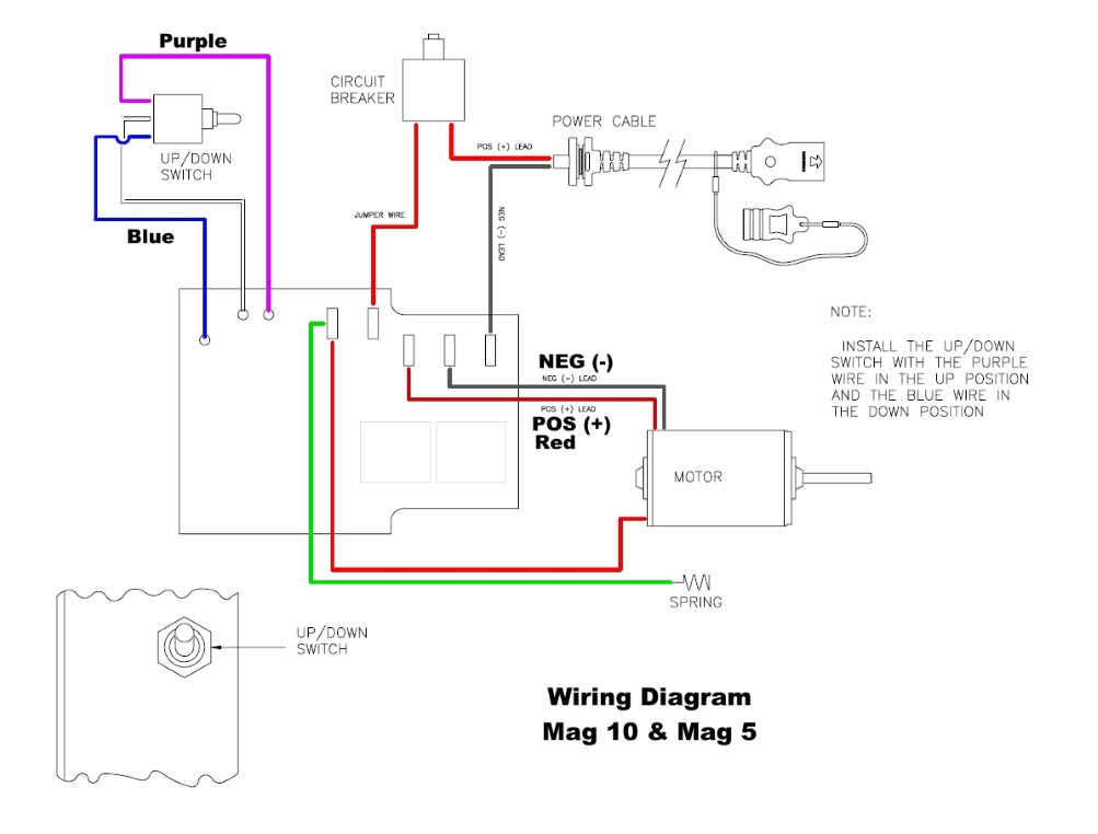
mag 10 5 wiring diagram, image source: www.fish307.com
SWITCH, image source: www.ehx.com
mustang87 92 20powerwindowwiring gif, image source: asfbconference2016.org
98826, image source: forums.parallax.com

EZ_3PDT_WIRING, image source: elsalvadorla.org
MOTOR_GUIDE_MICRO_SWITCH_i3, image source: www.odicis.org
200931231537_PWM_Scooter_controller_setup, image source: www.modifiedpowerwheels.com

alternative stompbox wiring 01, image source: diystrat.blogspot.com

2014 dodge ram wiring diagrams wiring diagram images database with 2009 dodge ram wiring diagram, image source: efcaviation.com

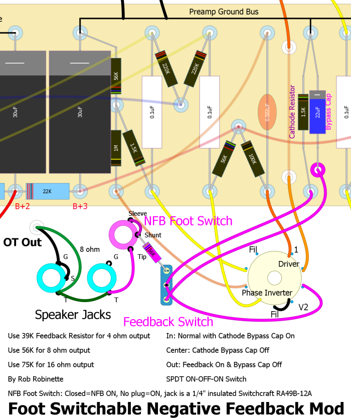
5e3_Feedback_Foot_Switch, image source: robrobinette.com

hc, image source: www.odicis.org
minnkota maxxum breakdown, image source: www.pinsdaddy.com
881170A20, image source: www.marineengine.com
2000 Dodge Avenger Fuse Box Diagram, image source: circuitswiring.com

MP35037________UN01NOV04, image source: www.justanswer.com

2012 10 12_184700_2012 10 12_124324, image source: www.justanswer.com

hqdefault, image source: www.youtube.com
2010 08 01_214419_100_1014, image source: www.justanswer.com

0 comments:
Post a Comment