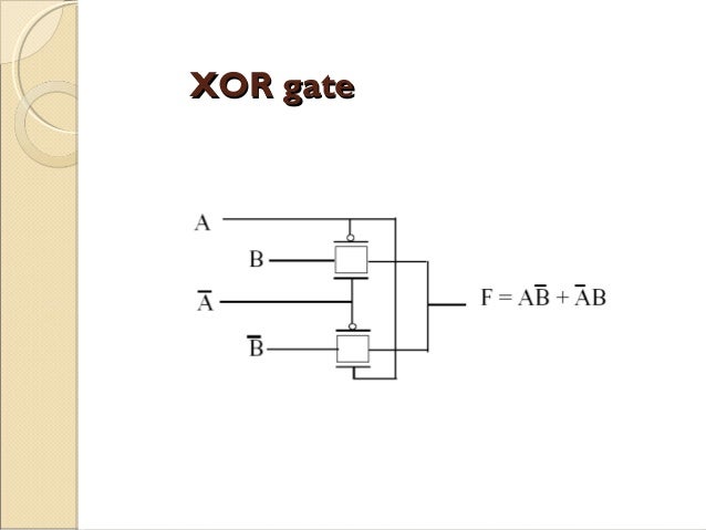
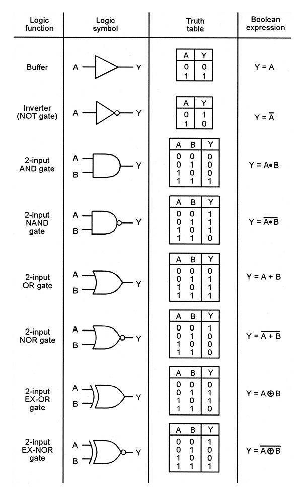
Xor Gate Circuit Diagram There are two symbols for XNOR gates one with distinctive shape and one with rectangular shape and label The distinctive symbol for the XNOR gate is that of the XOR gate with an added inversion bubble Xor Gate Circuit Diagram work is licensed under a Creative Commons Attribution NonCommercial 2 5 License This means you re free to copy and share these
teahlab finite state machine Serial AdderA serial adder is a digital circuit that can add any two arbitrarily large numbers using a single full adder Beyond presenting the serial adder circuit the interactive digital system at the top of the page also demonstrates how we use two 4 bit shift registers to store the addends and the sum of the addition Xor Gate Circuit Diagram learnabout electronics Digital dig21 phpDigital Logic Seven basic logic gates and how they work Logic gate animation vlsiwizard blogspot design clock divide by 3 circuit with htmlJan 03 2008 Nick said On the time nuts mailing list this topic came up and a solution with two D FFs and a single XOR gate was presented Configure each of the two Ds as a divide by two D fed from Q
teahlab 4 bit counter modulo 16 D flipflopa counter is a logic circuit that counts as time passes The interactive circuit above is a four bit counter that is designed to count from zero Xor Gate Circuit Diagram vlsiwizard blogspot design clock divide by 3 circuit with htmlJan 03 2008 Nick said On the time nuts mailing list this topic came up and a solution with two D FFs and a single XOR gate was presented Configure each of the two Ds as a divide by two D fed from Q satsleuth Schematics aspxElectronic Circuit Schematics Note that all these links are external and we cannot provide support on the circuits or offer any guarantees to their accuracy
Xor Gate Circuit Diagram Gallery
images of xor gate circuit diagram introduction to logic gates, image source: www.diaoyurcom.com


173079, image source: www.hindawi.com
th?id=OGC, image source: www.petervis.com

th?id=OGC, image source: www.petervis.com

.PNG)
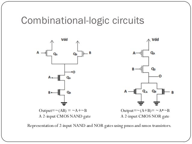
NOR_gate_(CMOS_circuit), image source: commons.wikimedia.org
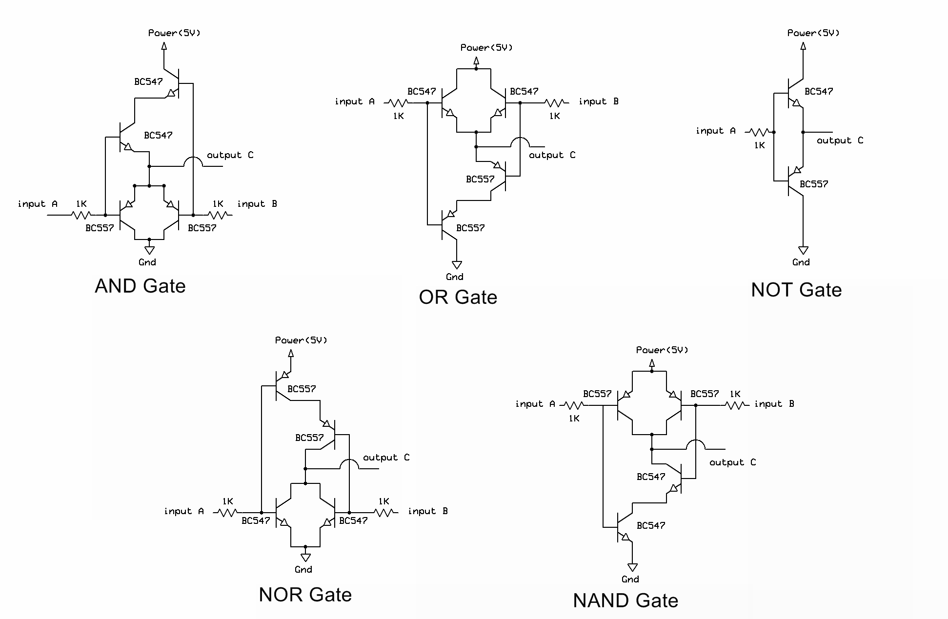
Logic Gates using Transistors, image source: electrosome.com
pass transistor logic 16 638, image source: www.slideshare.net

cmos flip flop, image source: www.indiabix.com
04146, image source: www.allaboutcircuits.com

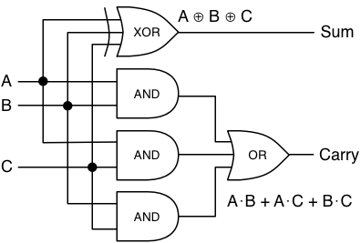
full adder simple, image source: robey.lag.net
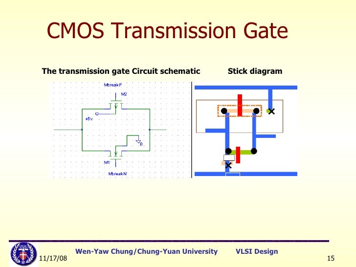
lect5stickdiagramlayoutrules 15 728, image source: vesselyn.com
NV_0407_Marston_Figure3, image source: www.nutsvolts.com
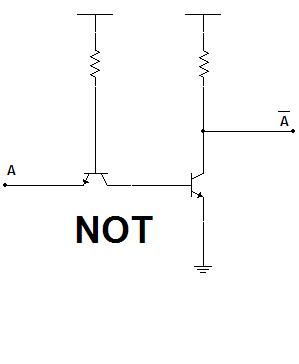
Puertas_NOT_con_transistores, image source: commons.wikimedia.org
vlsi stick daigram jce 16 638, image source: www.slideshare.net

Realization of Half Adder using NOR Gates, image source: www.electronicshub.org

binary to gray converter using xor 5 638, image source: www.slideshare.net
cmos logic circuits 11 638, image source: www.slideshare.net
Logic+Diagram+of+BCD to Excess 3+Code+Converter, image source: estrategys.co


1920px XNOR_ANSI_Labelled, image source: simple.wikipedia.org
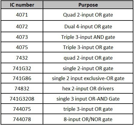
frequently used ics, image source: www.electronicshub.org


0 comments:
Post a Comment