Electronic Centrifugal Switch Circuit Diagram fsignitions uploads 6 VOLT PG ZIPPER INSTALLATION first street ignitions 220 north 1st street ponca city ok 74601 ph fax 580 762 8322 email fsignitions cableone fsignitions fsi zipper electronic ignition centrifugal advance distributor Electronic Centrifugal Switch Circuit Diagram edutekinstrumentation electrical training equipment htmlElectrical Training Equipment Electrical Engineering Equipments are sought for all engineering related operations They have wide range of applications and simplify the complexities to great extent
machineryequipmentonline electric equipment forward re verse Developing a Wiring Diagram The same basic procedure is used to develop a wiring diagram from the schematic as was followed in the previous chapters Electronic Centrifugal Switch Circuit Diagram transfer switch is an electrical switch that switches a load between two sources Some transfer switches are manual in that an operator effects the transfer by throwing a switch while others are automatic and trigger when they sense one of the sources has lost or gained power ufixit Repair TipsThis is the most common symptom we hear on all brands of dryers One of the appliance parts most of us suspect first is the heating element see common Whirlpool elements below but there are several other appliance parts on the dryer and one item that is not on the dryer that can produce the same symptom You will save time energy and money
industrial electronics eed5th 9 html1 Introduction In recent years there has been a steady evolution toward the use of solid state components in industrial control This does not mean that all electromechanical devices will be replaced but they will share a smaller part of the industrial control spectrum in the future Electronic Centrifugal Switch Circuit Diagram ufixit Repair TipsThis is the most common symptom we hear on all brands of dryers One of the appliance parts most of us suspect first is the heating element see common Whirlpool elements below but there are several other appliance parts on the dryer and one item that is not on the dryer that can produce the same symptom You will save time energy and money gardentractorpullingtips ignition htmIgnition Solutions Spark ignited engines requires a spark to initiate burning of the air fuel mixture in the combustion chamber The spark in each cylinder is provided by a spark plug and is actually a flow of electrical current through the air and fuel vapor between the closely spaced electrodes of the spark plug
Electronic Centrifugal Switch Circuit Diagram Gallery
US06271639 20010807 D00002, image source: elsalvadorla.org
patent us6288516 food processor motor controller google patents drawing_circuit diagram motor_230v motor wiring diagram 3 wire am receiver circuit electric winding speed driver contactor_850x548, image source: farhek.com
180v dc motor speed control circuit diagram juanribon com_circuit diagram of motor_wire schematic led light diagram joining electrical wires wiring tutorial bass pickup diagrams symbol, image source: farhek.com
new circuits page next gr dc motor controller and tachometer_sensing circuits_zener diode polarity wire precision resistor the wiring diagram limiter types tone generator circuit can you, image source: farhek.com
component ac motor control circuit diagram single phase bidirectional rotation of an induction with a wireless remote basic_circuit diagram motor_speed control dc motor e, image source: farhek.com
0900c15280048e1f, image source: www.autozone.com

fig26, image source: www.pinsdaddy.com
Mydax Air Cooled Liquid Chiller PID Mechanical Schematic Diagram for 1M16A Model, image source: 123wiringdiagram.online

Ac Motor Centrifugal Switch1, image source: www.odicis.org
patent us4017776 reversible shaded pole motor and control drawing_shaded pole motor_schneider electric contactor wiring diagram 3ph motor single phase schematic power switch circuit c, image source: gsmportal.co

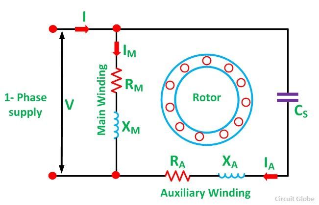
Permanent Split Capacitor Motor fig, image source: circuitglobe.com

submersible+water+pump+controller+circuit, image source: www.homemade-circuits.com
gmf amps gmfamps twitter_symbol for amps_electronic circuit diagram symbols schematic drawing house wiring adjustable resistor symbol generator electric chart automotive, image source: billigfluege.co

o65P5, image source: diy.stackexchange.com
transmission gate, image source: www.odicis.org

315d3c01e276b74619ec07fcfabc73d7, image source: www.pinterest.com

pict pump symbols design elements pumps, image source: www.odicis.org

ref_pg4, image source: elsalvadorla.org
ref_pg1, image source: www.iprocessmart.com


0 comments:
Post a Comment