
Intermatic Timer Switch Wiring Diagram amazon Switches Wall Switches Timer SwitchesProduct description The Intermatic ET1105C 24 Hour Electronic Time Switch allows a program to be repeated on a daily basis This great time switch provides dependable and uncomplicated performance with to the minute programming for extremely accurate load control while also offering reduced energy costs Intermatic Timer Switch Wiring Diagram T101 Series 40 Amp 125 Volt The Intermatic 40 Amp 125 Volt SPST Electromechanical Time Switch with Indoor Enclosure is designed for industrial commercial and residential applications This is an CSA certified product for safety It is ideal for general purpose usage Price 46 53Availability In stock
uedata amazon Switches Wall Switches Timer SwitchesIntermatic T104R 208 277 Volt DPST 24 Hour Mechanical Time Switch with Outdoor Case Intermatic Timer Switch Wiring Diagram repairfaq sam micfaq htmBack to Microwave Oven Repair FAQ Table of Contents Microwave Oven Troubleshooting SAFETY The following applies to microwave oven troubleshooting once the cabinet cover is removed There is also safety information on inyopools Crystal Pure Salt SystemA Answered on 4 24 2018 by InyoPools Product Specialist Patrick P The Heavy duty is the same system as the standard but with two main advantages 1 The warranty is 3 year on the Heavy Duty Vs 2 years on the Standard 2
poolcenter c intermaticTimersIntermatic Timers Intermatic Swimming Pool Pump Timers are the standard industry favorite for reliable control of pool pumps outdoor lighting pool heaters and more Intermatic Timer Switch Wiring Diagram inyopools Crystal Pure Salt SystemA Answered on 4 24 2018 by InyoPools Product Specialist Patrick P The Heavy duty is the same system as the standard but with two main advantages 1 The warranty is 3 year on the Heavy Duty Vs 2 years on the Standard 2
Intermatic Timer Switch Wiring Diagram Gallery
leviton timer switch wiring diagram copy leviton ltb30 1lz fan timer install youtube maxresdefault switch of leviton timer switch wiring diagram, image source: www.diagramschematics.us

p1353me 2 speed motor 500 wiring diagram intermatic clock timer circuit instructions t103 switch how to wire t104 t101p3 120v for t101m t104m eh40 t101 sprinkler t101r t10404r pool, image source: altrushare.com


wiring diagram hot water heater timer new new electric water heater wiring diagram hot dolgular for tank of wiring diagram hot water heater timer, image source: wiringdiagram.karaharmsphotography.com
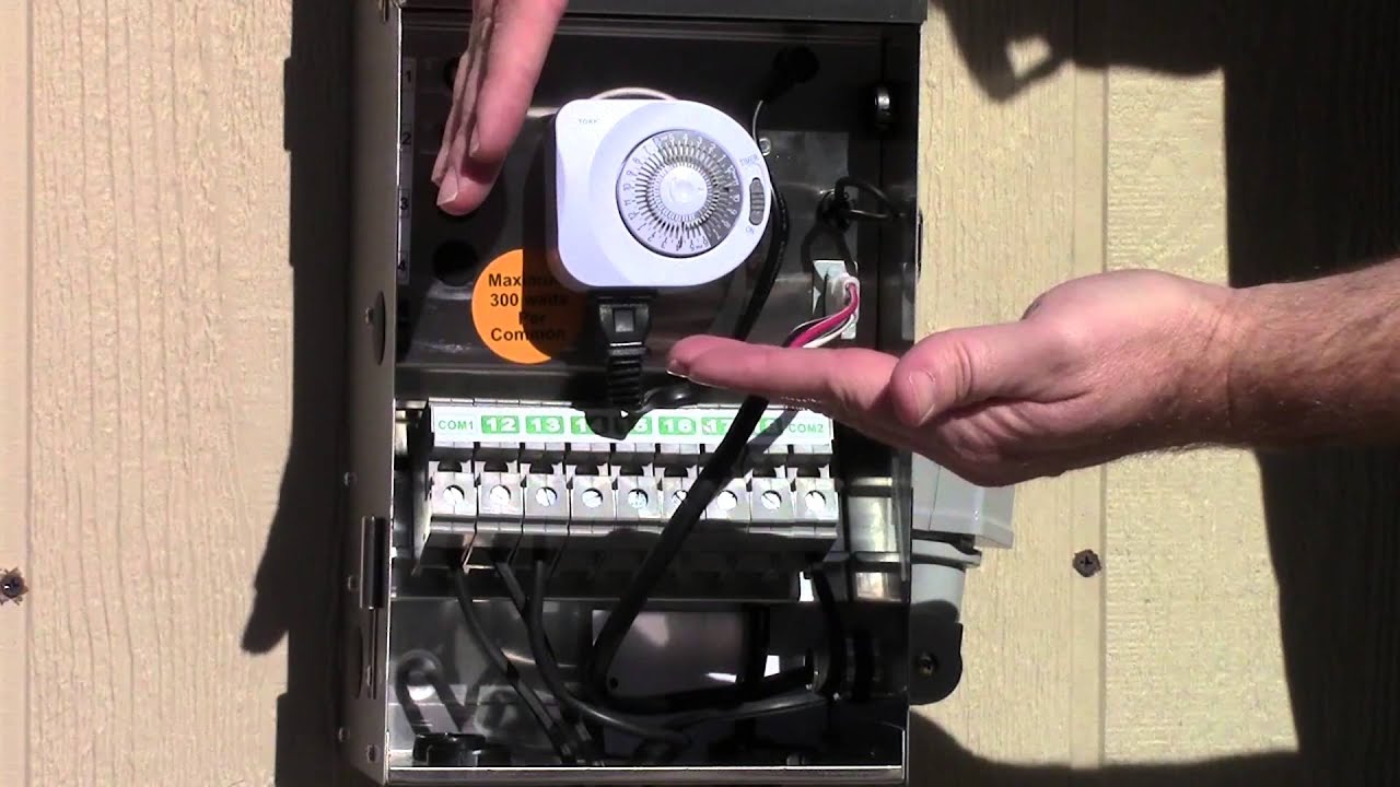
need help hooking up pool pump relay switch intermatic mechanical timer 20130527 154411 0 1 wiring diagram clock circuit t104 sprinkler instructions how to wire for t104m t101r t10, image source: altrushare.com


3 way and 4 way wiring diagrams with multiple lights do it within multiple light switch wiring diagram, image source: elsalvadorla.org

2014 01 20_184615_defiant_timer, image source: www.myomedia.co
pool timer wiring diagram swimming for intermatic, image source: agnitum.me

intermatic pool timer with gfi, image source: www.diaoyurcom.com

how to wire intermatic t104 and t103 and t101 timers of time switch wiring diagram, image source: elsalvadorla.org

engine on and off switch velosolex horn contractor flywheel magneto ezgo txt wiring diagram grey black pipes continues, image source: www.easyhomeview.com

awesome 5 pin relay wiring diagram electrical and wiring of 5 pin bosch relay wiring diagram, image source: swarovskicordoba.com

three phase plug wiring diagram elegant 3 phase electrical wiring of three phase plug wiring diagram, image source: swarovskicordoba.com


30688d1398570192 pool pump timer wiring questions motor overheats tork 1103, image source: www.doityourself.com
Screen Shot 2015 10 15 at 4, image source: panicattacktreatment.co

cooling fan wiring diagram schema for laptop circuit electric harness car control pt cruiser p0481 2 malfunction p0482 3 automatic components toyota kit 1 jetta manual cpu 2002 tra, image source: altrushare.com

maxresdefault, image source: www.youtube.com
simple science project parallel and serial circuits cg img 0750 breadboard circuit drawing program amplifiers multisim sample components of integrated e resistor connections resist, image source: altrushare.com

rdc 1 dp aftermarket packaged remote livewell drain control valve 500_4, image source: www.odicis.org

LMRC 210 Series 5, image source: literitecontrols.com


0 comments:
Post a Comment